The Goal:
Description:
My instructable is a battery voltage tester. This product allows a user to place a battery (1.5V or less) into the battery compartment and find the voltage remaining in the battery on the two 7-segment displays. The voltage of the battery enters a transistor and not gate which checks if there is current in the battery, if there is then it relays that to the Arduino. The Arduino displays the voltage accurate to two digits on the two 7-segment displays. The voltage can also be found on the Serial Monitor on the Arduino software accurate to two decimal places.
- Read from analog pin one
- Multiply the reading by 0.0048 to create a voltage value.
- Display the voltage accurate to two digits on the two 7-segment displays.
- Display the rest of the digits on the serial monitor of the Arduino software.
- Repeat indefinitely.
Description:
My instructable is a battery voltage tester. This product allows a user to place a battery (1.5V or less) into the battery compartment and find the voltage remaining in the battery on the two 7-segment displays. The voltage of the battery enters a transistor and not gate which checks if there is current in the battery, if there is then it relays that to the Arduino. The Arduino displays the voltage accurate to two digits on the two 7-segment displays. The voltage can also be found on the Serial Monitor on the Arduino software accurate to two decimal places.
Parts Needed:
- Arduino Uno microcontroller – Measures the voltage of the battery and forwards that onto the software and 7-segment display.
- Breadboard – Links all the components and Arduino together.
- 2x 7-segment display – Displays the voltage of the battery in integer format.
- Transistor – Allows current to pass through from the battery holder to the Arduino only if there is a voltage in the battery holder; if there is no current in the battery holder then it simply grounds the A1 voltage checking pin, so there is a reading of zero.
- 2x 74LS47 – Decoder chips that convert input from the Arduino into output for the 7-segment display; reduces the number of digital pins required.
- 2x 330ohm resistors – Resists current going into 7-segment display in order to stop it from overheating.
- Battery holder – Holds the AA battery that is going to be checked for voltage.
- 74LS04 Integrated circuit – This NOT-gate has the output of the battery holder as its input and the output of the NOT-gate goes to the transistor. When the battery holder has nothing in it then the transistor is on and allows the A1 to be grounded, which gives a reading of zero. However, when the battery holder has a voltage then the transistor does not allows current through and the A1 is grounded after it goes through the battery, which gives a voltage value to the Arduino.
- Wires – At least 15 long wires and 15 short wires are required to connect the entire project together.
- Solder (Optional) – If you want to get real freaky then you can use a soldering iron and solder to permanently fix the connections together.
How To Build:
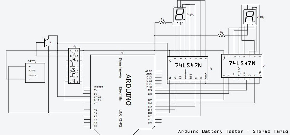
Step 1: Wire the components together using the following circuit schematic diagram.
Step 1: Wire the components together using the following circuit schematic diagram.
Step 2: Use the following sketch on the Arduino software. Modify it as appropriate. 0.35 V are added to the total voltage as some voltage is lost when the output of the battery is put into the not gate and the transistor; this negates any effect of that lost voltage.
//Sheraz Tariq
byte ziffer[11][4] = { { 0,0,0,0 }, // = 0
{ 0,0,0,1 }, // = 1
{ 0,0,1,0 }, // = 2
{ 0,0,1,1 }, // = 3
{ 0,1,0,0 }, // = 4
{ 0,1,0,1 }, // = 5
{ 0,1,1,0 }, // = 6
{ 0,1,1,1 }, // = 7
{ 1,0,0,0 }, // = 8
{ 1,0,0,1 }, // = 9
{ 1,1,1,1 } // off
};
void setup(){
Serial.begin(9600);
pinMode(2, OUTPUT);
pinMode(3, OUTPUT);
pinMode(4, OUTPUT);
pinMode(5, OUTPUT);
digitalWrite(2, 1);
digitalWrite(3, 1);
digitalWrite(4, 1);
digitalWrite(5, 1);
pinMode(6, OUTPUT);
pinMode(7, OUTPUT);
pinMode(8, OUTPUT);
pinMode(9, OUTPUT);
digitalWrite(6, 1);
digitalWrite(7, 1);
digitalWrite(8, 1);
digitalWrite(9, 1);
delay(2000);
}
void ziffer_schreiben(byte digit) {
digitalWrite(2,ziffer[digit][3]);
digitalWrite(3,ziffer[digit][2]);
digitalWrite(4,ziffer[digit][1]);
digitalWrite(5,ziffer[digit][0]);
}
void ziffer_sheraz(byte digit) {
digitalWrite(6,ziffer[digit][3]);
digitalWrite(7,ziffer[digit][2]);
digitalWrite(8,ziffer[digit][1]);
digitalWrite(9,ziffer[digit][0]);
}
void loop(){
float numbers =0;
float secondDigit =0;
float sensorValue = analogRead(A1);
float voltage1 = sensorValue * (5/1023.0);
numbers = voltage1+0.35;
if (numbers >=1) {
Serial.println(numbers);
/////////////
ziffer_schreiben(1) ;
secondDigit = (numbers-1)*10;
ziffer_sheraz(secondDigit) ;
/////////////
}
if ((numbers < 1) && (numbers > 0.09)){
if (numbers < 0.09) {
Serial.println(0);
}
else{
Serial.println(numbers);
}
/////////////
ziffer_schreiben(numbers) ;
/////////////
secondDigit = (numbers)*10;
ziffer_sheraz(secondDigit) ;
}
if (voltage1 < 0.09){
numbers =0;
ziffer_schreiben(numbers) ;
secondDigit = (numbers)*10;
ziffer_sheraz(secondDigit) ;
}
}
Step 3: At this point you have essentially completed your project. Now simply plug in your Arduino into your computer to upload the sketch. Use the serial monitor if necessary to view your voltage. Happy voltage testing!
Reference:
The inspiration for this project came from the following pdf; this original instructable involved three LEDs that showed the power left in the battery, I modified it to show the actual voltage left in the battery using 7 segment displays. My circuit schematic is very different from this one as my project is more complex than this one. http://nostarch.s3.amazonaws.com/arduino_project6.pdf
